As network demands continue to grow in scale and complexity, the need for efficient, scalable, and flexible VPN solutions becomes paramount. Ethernet VPN (EVPN) combined with Segment Routing (SR) over Intermediate System to Intermediate System (IS-IS) in a multi-domain environment, with the addition of BGP Label Unicast (BGP-LU), offers a sophisticated solution for Layer 2 (L2VPN) and Layer 3 (L3VPN) services. In this blog, we will explore how EVPN-based VPN services function over Multi-Domain ISIS-SR with BGP-LU, and the advantages this integration brings to large-scale network deployments.
Multi-Domain ISIS-SR
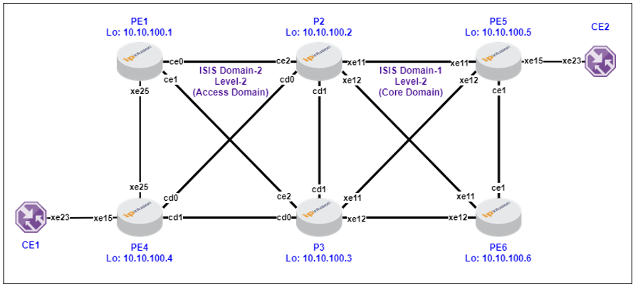
In large-scale networks, using a single IS-IS domain may not be feasible due to scalability and management concerns. Multi-Domain IS-IS addresses this by dividing the network into multiple IS-IS domains. Each domain independently runs its own IS-IS-SR instance, while inter-domain routing is handled through BGP-LU.
Role of BGP-LU (BGP Label Unicast)
BGP Label Unicast (BGP-LU) is used for distributing MPLS labels along with IP prefixes across different domains. This approach is crucial in a multi-domain environment, as it ensures seamless label distribution and forwarding across different SR domains. BGP-LU extends BGP by adding the ability to advertise MPLS labels, enabling label switching across diverse network segments.
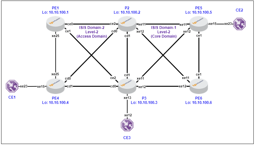
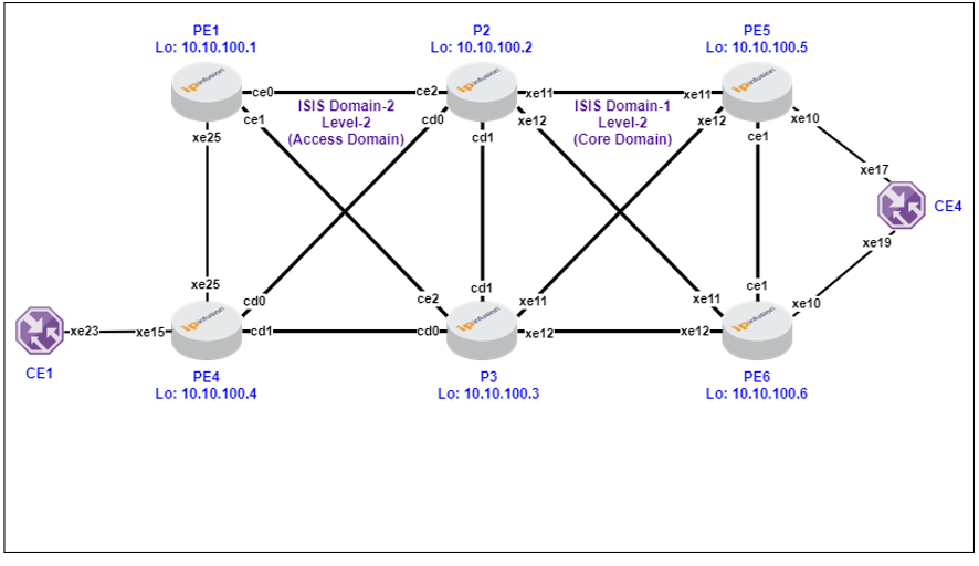
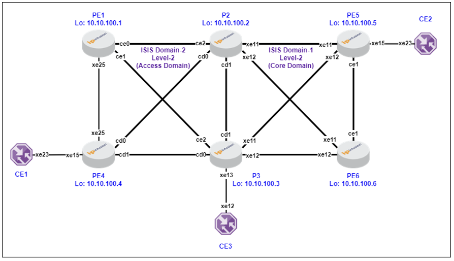
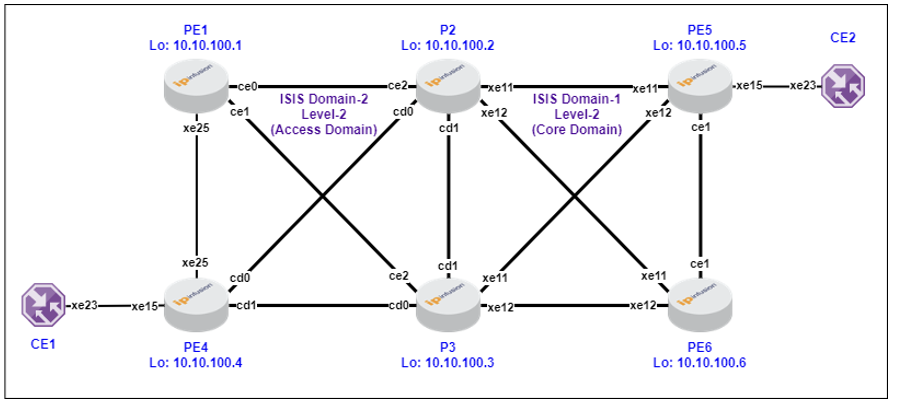
Multi-Domain ISIS-SR with BGP-LU Underlay
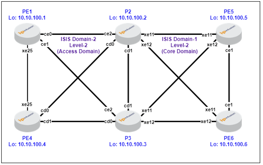
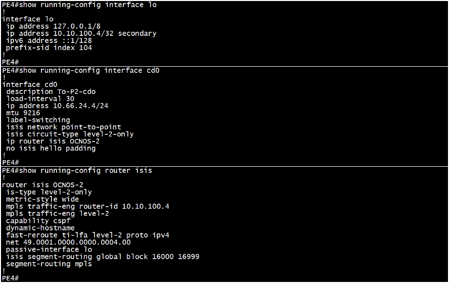
Sample ISIS-SR Configuration from PE4 device (as Edge):
This includes the configuration for loopback and physical interfaces, along with the router’s ISIS-SR.
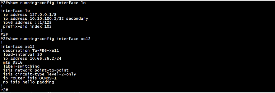
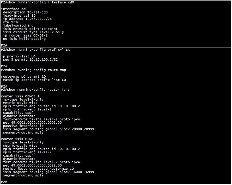
Sample ISIS-SR Configuration from P2 device (as ABR):
This includes the configuration for loopback and physical interfaces, along with the router’s ISIS-SR. Currently, in OcNOS, the same loopback IP address cannot be used across multiple IGP processes. So, we assign the loopback IP address to one IGP process and then redistribute it into another IGP process using redistribute connected with prefix-list and route-map.
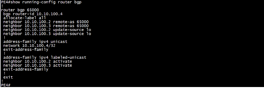
Sample MP-BGP Configuration from PE4 device (as Edge):
This includes the MP-BGP configuration on edge device.
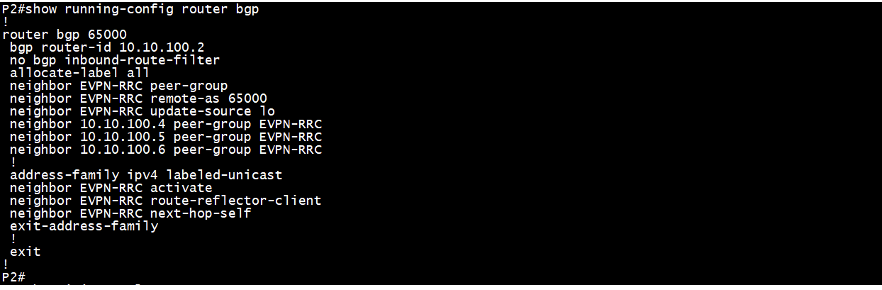
Sample MP-BGP Configuration from P2 device (as ABR inline RR):
This includes the MP-BGP configuration on ABR as inline RR device.
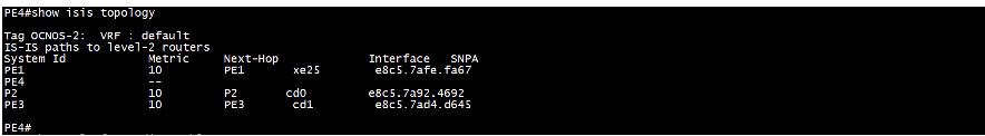
Validation ISIS-SR from PE4 device (as Edge):
This displays topology details including metrics and next-hop.
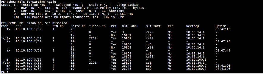
This ensures that MPLS Forwarding Table (FTN) entries are installed for the loopback addresses of all routers in the network. The command below provides details such as the outbound label (out-label), outbound interface (out-interface), next-hop, and other relevant information. It is crucial to perform this check on the source router. Along with the FTN entries installed from its own IGP domain, the router also includes FTN entries learned via BGP. If the same FTN is available from both IGP and BGP, the entry learned from IGP takes precedence.
This ensure the MPLS ILM-table (Incoming Label Mapping Table) entries installed for the loopback addresses of all routers in the network and the local link’s next-hop IP address. This command provides details such as the inbound label (in-label), outbound label (out-label), outbound interface (out-interface), next-hop, and more. It is essential to perform this check on the transit router. The router also includes ILM-table entries learned via BGP.
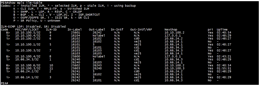
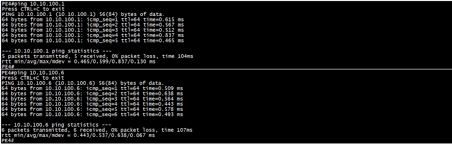
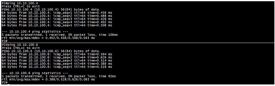
This is to check network connectivity using ping commands.
Validation ISIS-SR from P2 device (as ABR):
This displays topology details including metrics and next-hop.

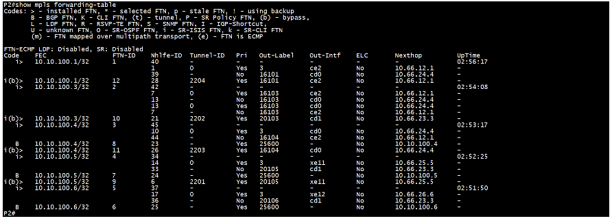
This ensure the MPLS Forwarding-table (FTN) entries installed for the loopback addresses of all routers in the network. Below command provides details such as the outbound label (out-label), outbound interface (out-interface), next-hop, and more. It is essential to perform this check on the source router. Along with the FTN entries installed from its own IGP domain, the router also includes FTN entries learned via BGP. If the same FTN is available from both IGP and BGP, the entry learned from IGP takes precedence.
This ensures the MPLS ILM-table (Incoming Label Mapping Table) entries installed for the loopback addresses of all routers in the network and the local link’s next-hop IP address. This command provides details such as the inbound label (in-label), outbound label (out-label), outbound interface (out-interface), next-hop, and more. It is essential to perform this check on the transit router. The router also includes ILM-table entries learned via BGP.
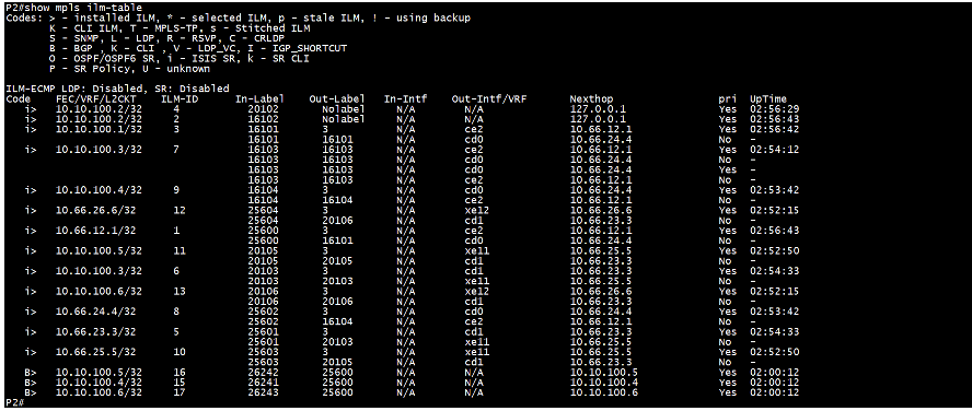
This is to check network connectivity using ping commands.
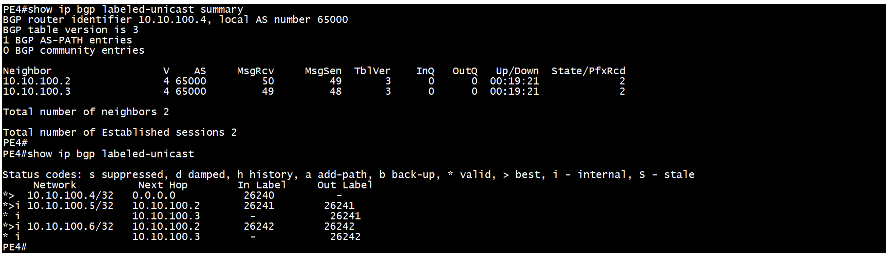
Validation MP-BGP (Labeled Unicast) from PE4 device (as Edge):
This verifies BGP neighborship for Labeled Unicast and L2VPN EVPN address family on edge device.
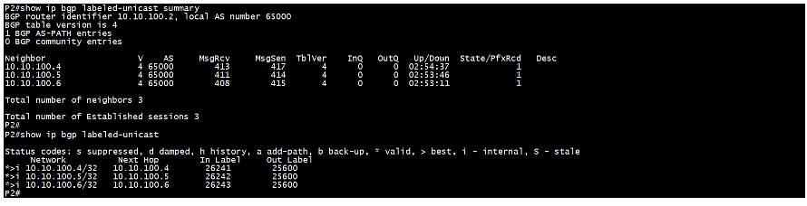
Validation MP-BGP (Labeled Unicast) from P2 device (as ABR inline RR):
This verifies BGP neighborship for Labeled Unicast and L2VPN EVPN address family on edge device.
EVPN ELINE SH aka EVPN VPWS SH Overlay
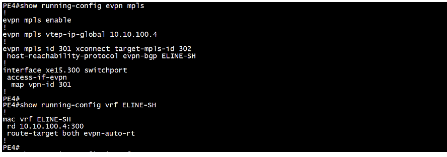
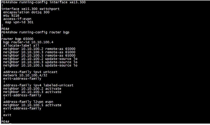
Sample Configuration from PE4 device:
We start by enabling EVPN MPLS and assigning a VTEP global IP address, which typically matches the loopback IP address. Next, we set up the EVPN-ELINE identifier, defining both the source identifier (local-id) and the target identifier (remote-id). We then map the MAC VRF to the EVPN-ELINE and associate the VPN ID (local-id) with the access interface that connects to the CE device. Finally, we enable the BGP EVPN address family to the neighbor PE device i.e. PE5 to establish communication.
Validation:
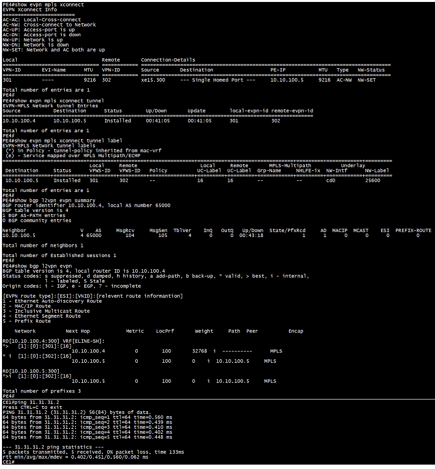
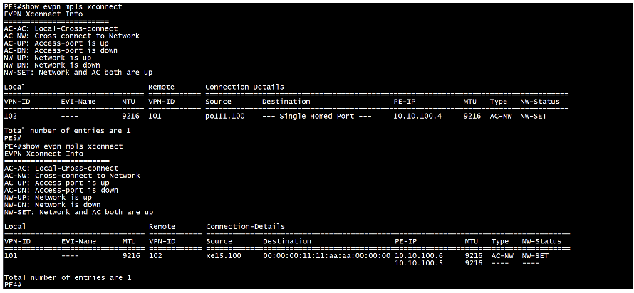
The command “show evpn mpls xconnect” checks the status of the connection, providing details such as whether the destination is single-homed or multi-homed with an ESI configured, the remote PE IP address, network type, and network status.
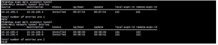
The command “show evpn mpls xconnect tunnel” verifies the tunnel status between the two PEs, including the local and remote EVPN IDs and the tunnel’s uptime.
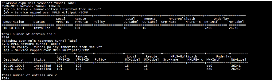
The command “show evpn mpls xconnect tunnel label” also provides the tunnel status, destination PE IP address, and local and remote EVPN IDs. Additionally, it shows the local and remote service labels, the outgoing network interface, and the transport label used on the network interface.
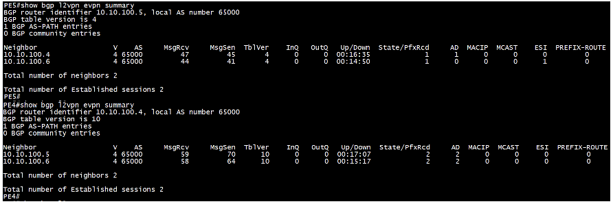
The command “show bgp l2vpn evpn summary” checks the BGP L2VPN EVPN neighbor relationship with the remote PE, including the total number of prefixes received and details of the corresponding EVPN route types.
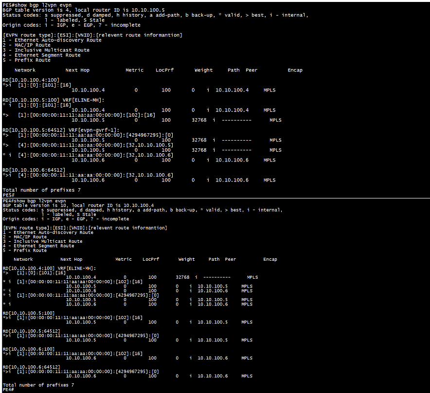
The command “show bgp l2vpn evpn” displays the routes sent and received between the PEs.
Finally, the “ping” command is used to verify end-to-end IP reachability between the CE devices.
EVPN ELINE MH aka EVPN VPWS MH Overlay
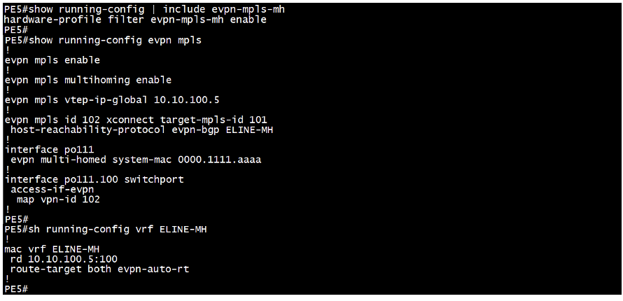
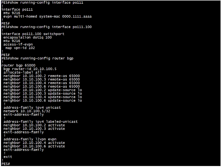
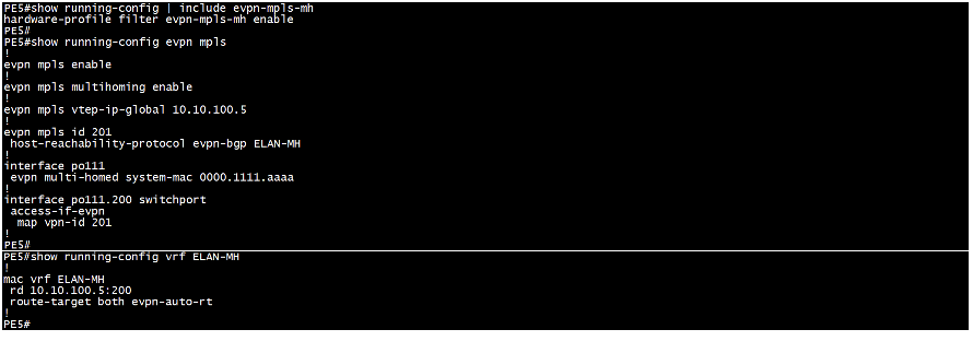
Sample Configuration from PE5 device:
In addition to the configuration used for EVPN ELINE SH, we need to enable multihoming for EVPN MPLS and respective hardware-profile filter on all the PEs that are multi-homed to the CE and assign a common ESI to the port channel interface connecting to the CE device.
Validation:
All validation commands are the same as those used for EVPN ELINE single-homed, with a few additional commands to verify the multihoming configuration. On PE4, we can observe that the destination is displayed with an ESI value, indicating it is multi-homed. We have included outputs from PE4 (SH) and PE5 (MH) for a parallel view.
Below, we can observe that two tunnels have been created from PE4, both with the same local and remote EVPN IDs.
Below, we can see that two tunnels have been established from PE4, both sharing the same local and remote EVPN IDs, along with their respective labels
On PE4, we can see that the EVPN route type-1, known as the “Ethernet A-D route” has increased from one to four because the destination PEs are multi-homed to the same CE device.
This provides details of the BGP EVPN routes that have been sent and received.
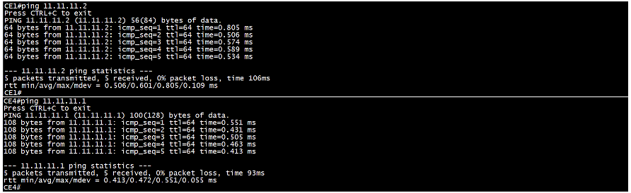
Finally, we use the “ping” command to verify end-to-end reachability between the CE devices.
EVPN ELAN SH aka EVPN VPLS SH Overlay
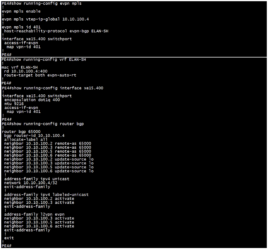
Sample Configuration from PE4 device:
We start by enabling EVPN MPLS and assigning a VTEP global IP address, which typically matches the loopback IP address. Next, we set up the EVPN-ELAN identifier. We then map the MAC VRF to the EVPN-ELAN identifier and associate the VPN ID with the access interface that connects to the CE device. Finally, we enable the BGP EVPN address family to the neighbor PE device to establish communication. BGP neighborship with remote PEs can be established directly or through a Route Reflector (RR).
Validation:
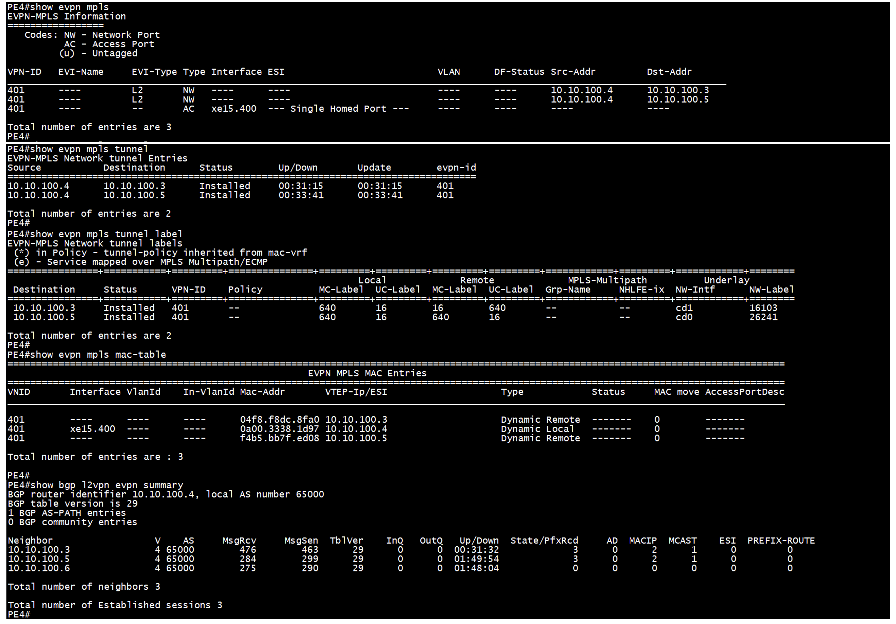
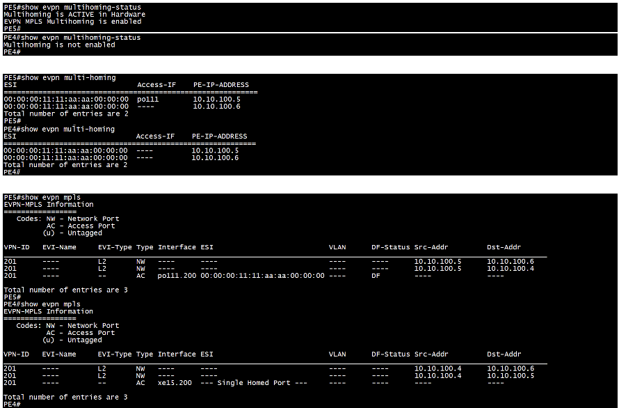
The command “show evpn mpls” checks the status of the connection, providing details such as whether the destination is single-homed or multi-homed with an ESI configured, the local and remote PE IP address, DF status.
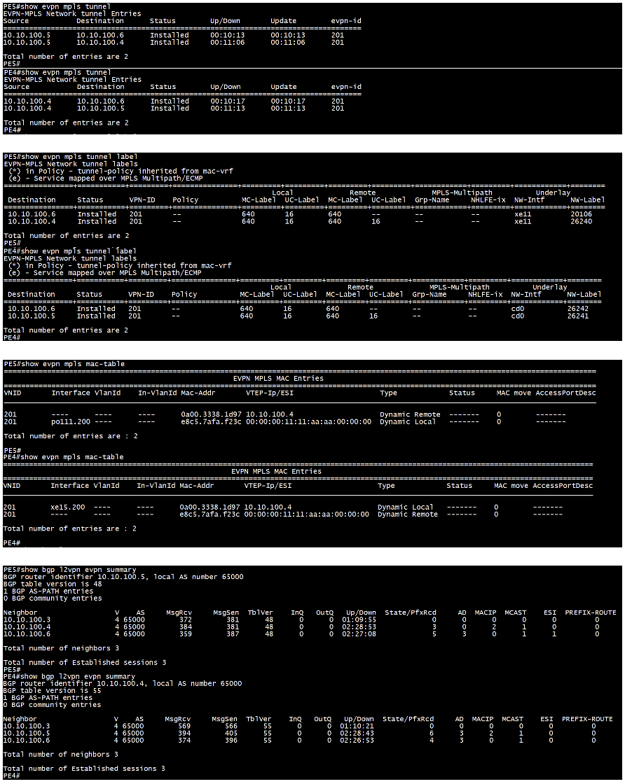
The command “show evpn mpls tunnel” verifies the tunnel status between the PEs, including the EVPN ID and the tunnel’s uptime.
The command “show evpn mpls tunnel label” also provides the tunnel status, destination PE IP address, and EVPN ID. Additionally, it shows the local and remote service labels, the outgoing network interface, and the transport label used on the network interface.
The command “show evpn mpls mac-table” displays MAC addresses learned both locally and from remote destination PE devices.
The command “show bgp l2vpn evpn summary” checks the BGP L2VPN EVPN neighbor relationship with the remote PE, including the total number of prefixes received and details of the corresponding EVPN route types. If the BGP peering is established through a Route Reflector (RR), the prefixes will be learned via the RR.
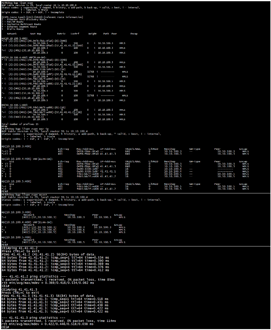
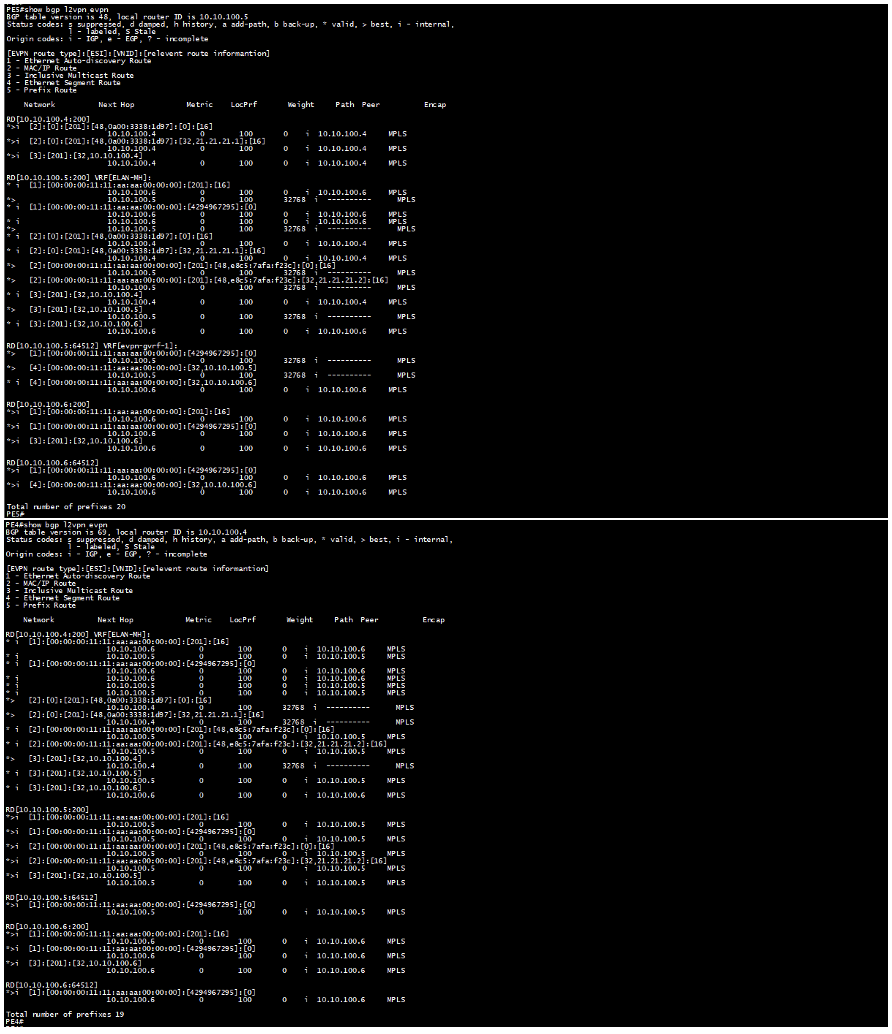
The command “show bgp l2vpn evpn” displays the routes sent and received between the PEs.
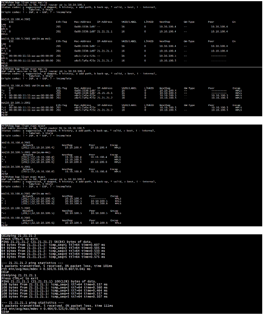
The command “show bgp l2vpn evpn mac-ip” displays the EVPN routes type 2 sent and received between the PEs.
The command “show bgp l2vpn evpn mcast” displays the EVPN routes type 3 sent and received between the PEs.
Finally, the “ping” command is used to verify end-to-end IP reachability between the CE devices.
EVPN ELAN MH aka EVPN VPLS MH Overlay
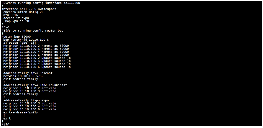
Sample Configuration from PE5 device:
In addition to the configuration used for EVPN ELAN SH, we need to enable multihoming for EVPN MPLS and respective hardware-profile filter on all the PEs that are multi-homed to the CE and assign a common ESI to the port channel interface connecting to the CE device.
Validation:
All validation commands are the same as those used for EVPN ELAN single-homed, with a few additional commands to verify the multihoming configuration. On PE5, we can observe the ESI value, indicating it is multi-homed. We have included outputs from PE4 (SH) and PE5 (MH) for a parallel view.
EVPN ETREE SH Overlay
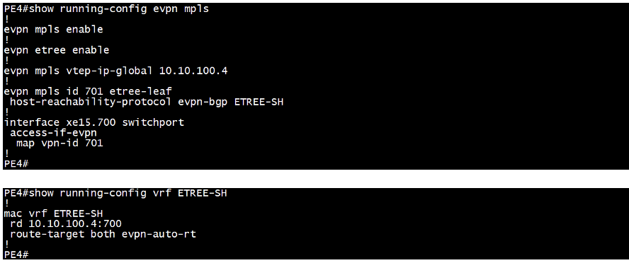
Sample Configuration from PE4 (Spoke SH) device & P3 (Hub) device:
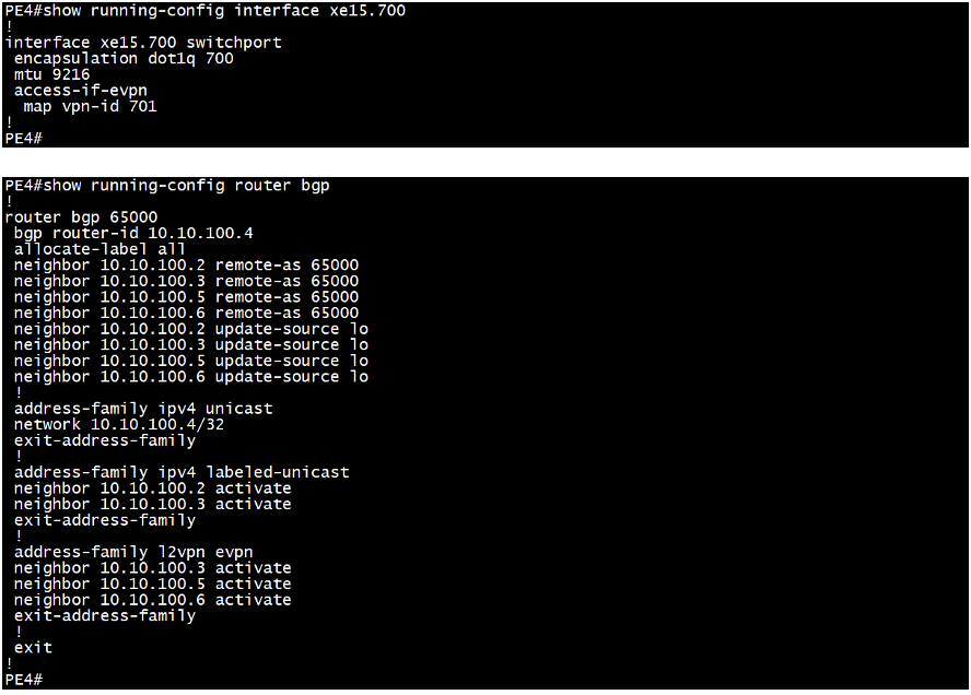
We start by enabling EVPN MPLS and assigning a VTEP global IP address, which typically matches the loopback IP address. Next, we set up the EVPN identifier and use the etree-leaf keyword on all spoke/leaf nodes. We then map the MAC VRF to the EVPN identifier and associate the VPN ID with the access interface that connects to the CE device. Finally, we enable the BGP EVPN address family to the neighbor PE device to establish communication. We have included outputs from PE4 (spoke) and P3 (hub) for a parallel view.
Validation:
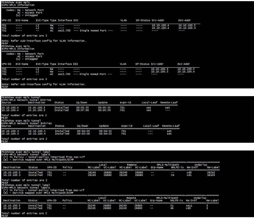
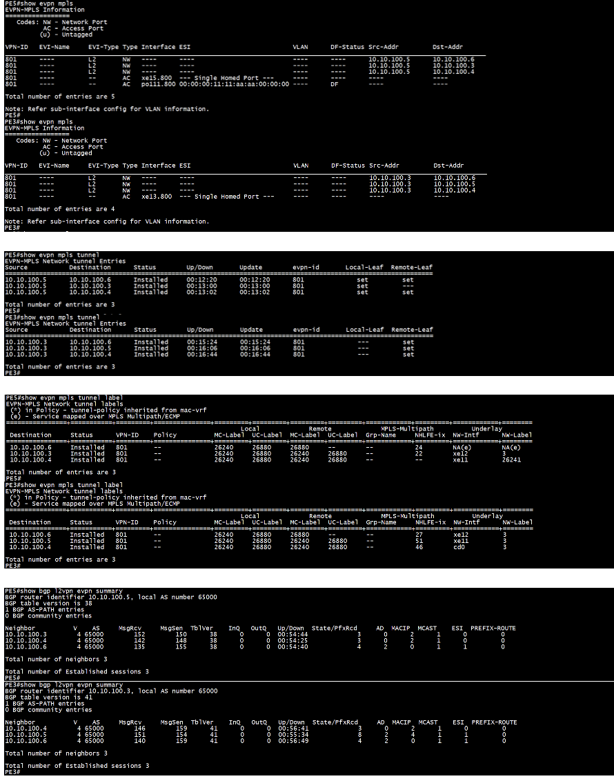
The command “show evpn mpls” checks the status of the connection, providing details such as whether the destination is single-homed or multi-homed with an ESI configured, the remote PE IP address, DF status.
The command “show evpn mpls tunnel” verifies the tunnel status between the PEs, including the EVPN ID, the tunnel’s uptime and local/remote leaf details.
The command “show evpn mpls tunnel label” also provides the tunnel status, destination PE IP address, and EVPN ID. Additionally, it shows the local and remote service labels, the outgoing network interface, and the transport label used on the network interface.
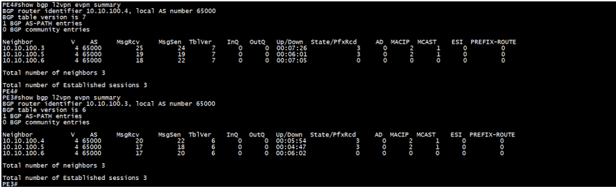
The command “show bgp l2vpn evpn summary” checks the BGP L2VPN EVPN neighbor relationship with the remote PE, including the total number of prefixes received and details of the corresponding EVPN route types. If the BGP peering is established through a Route Reflector (RR), the prefixes will be learned via the RR.
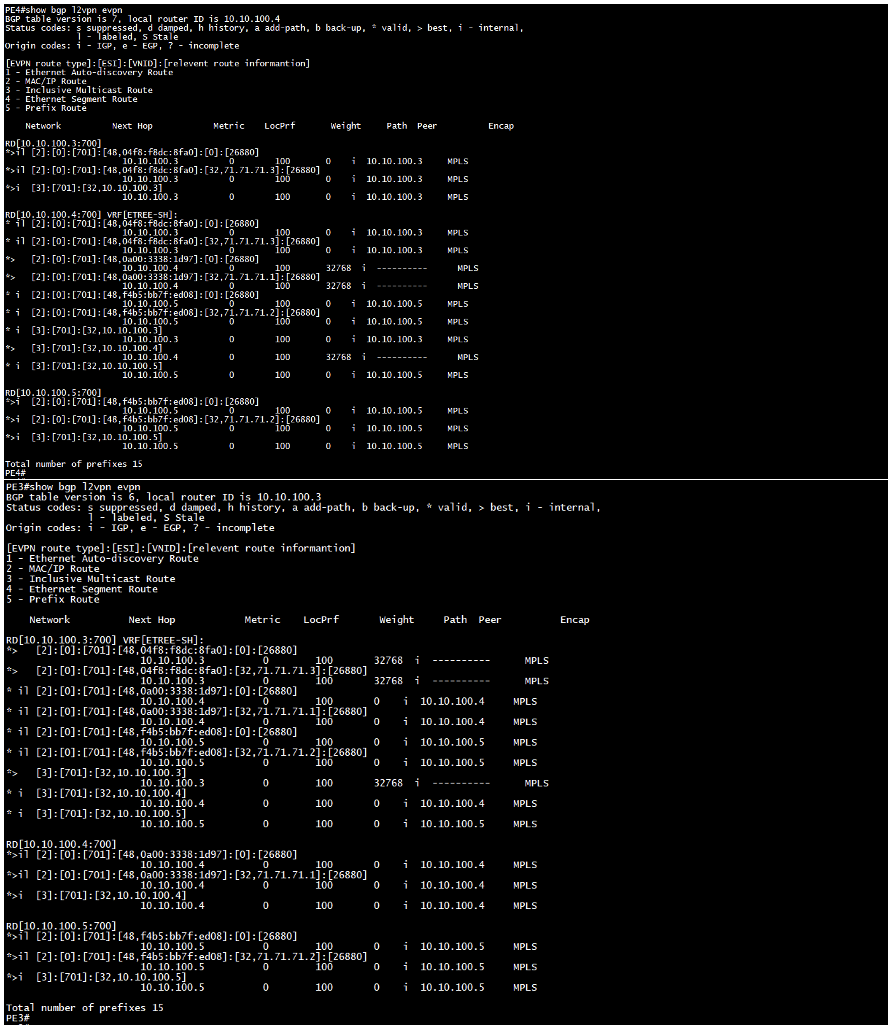
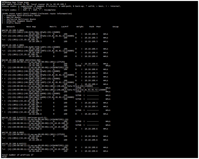
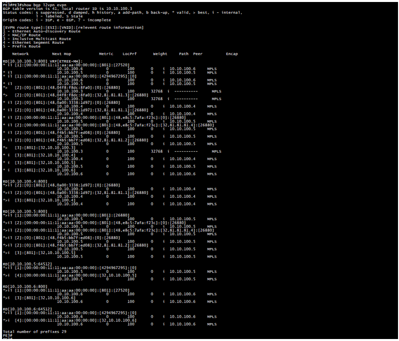
The command “show bgp l2vpn evpn” displays the routes sent and received between the PEs.
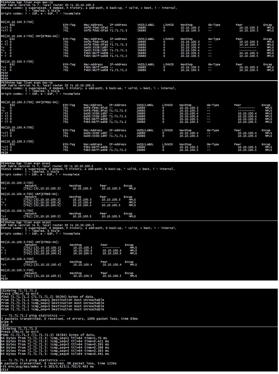
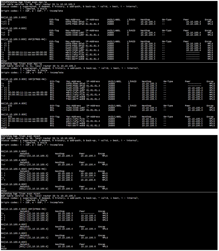
The command “show bgp l2vpn evpn mac-ip” displays the EVPN routes type 2 sent and received between the PEs.
The command “show bgp l2vpn evpn mcast” displays the EVPN routes type 3 sent and received between the PEs.
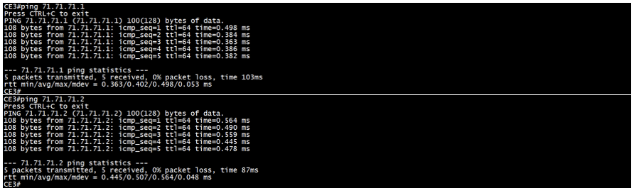
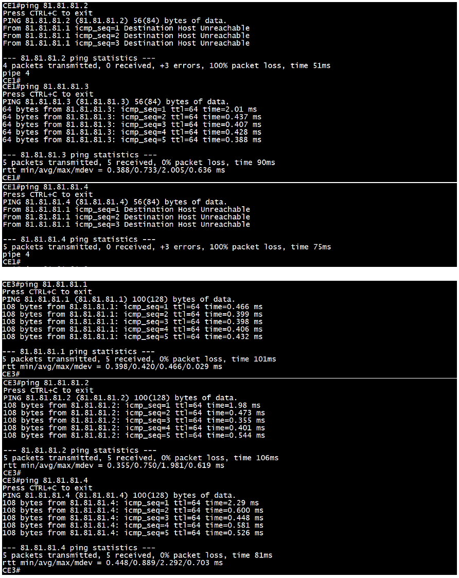
Finally, the “ping” command is used to verify end-to-end IP reachability between the CE devices.
EVPN ETREE MH Overlay
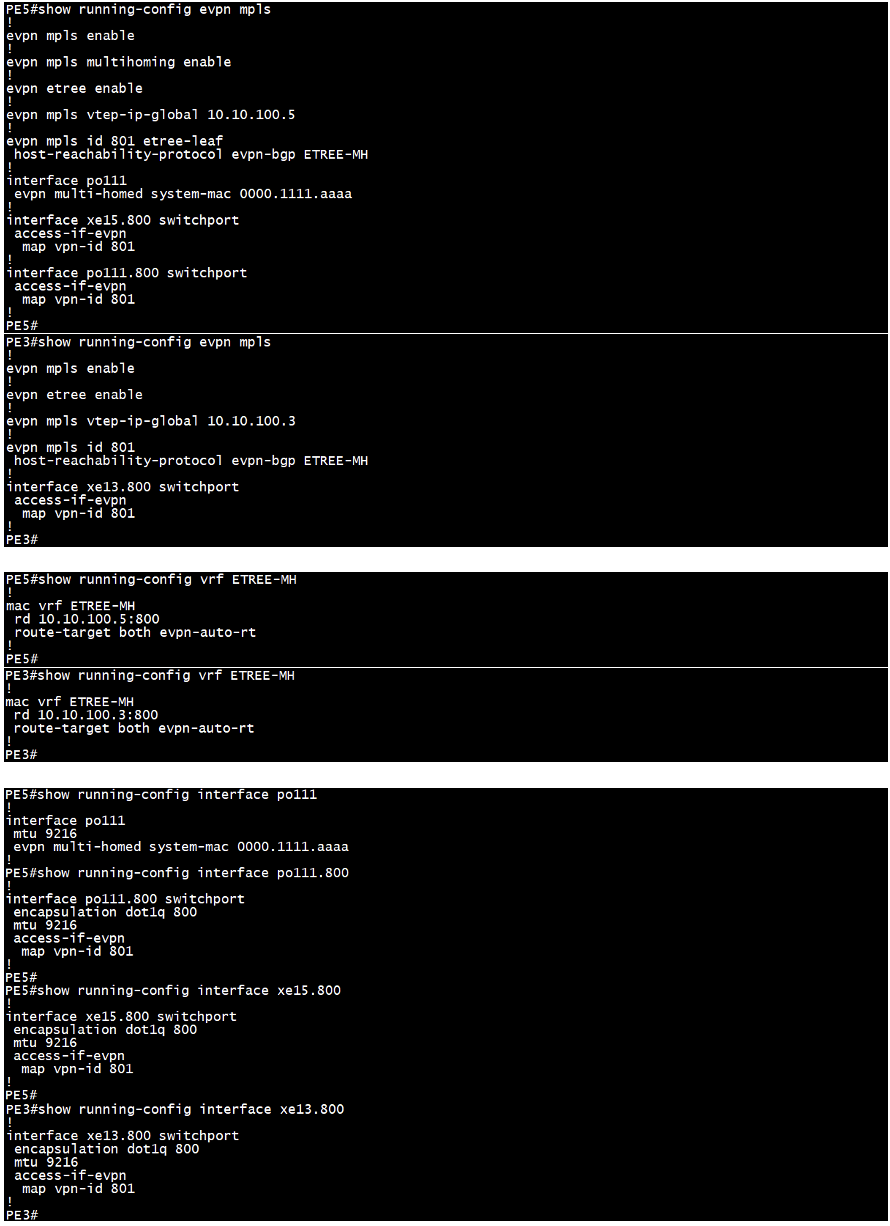
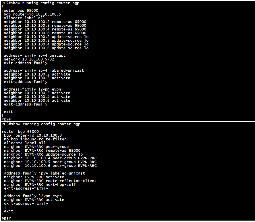
Sample Configuration from PE5 (Spoke MH) device & P3 (Hub) device:
In addition to the configuration used for EVPN ETREE SH, we need to enable multihoming for EVPN MPLS and respective hardware-profile filter on all the PEs that are multi-homed to the CE and assign a common ESI to the port channel interface connecting to the CE device.

Validation:
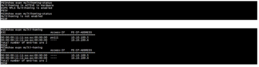
All validation commands are the same as those used for EVPN ETREE single-homed, with a few additional commands to verify the multihoming configuration. On PE5, we can observe the ESI value, indicating it is multi-homed. We have included outputs from PE5 (Spoke MH) and P3 (Hub) for a parallel view.
EVPN L3VPN Overlay
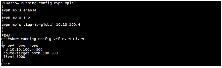
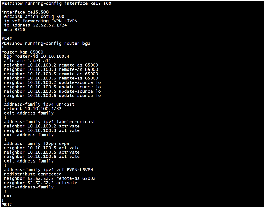
Sample Configuration from PE4 device:
We begin by enabling EVPN MPLS, IRB, and assigning a VTEP global IP address, typically matching the loopback IP. Then, we configure an IP VRF with L3VNI. Next, we assign the VRF and IP address to the access interface connecting to the CE device. Finally, we enable the BGP EVPN address family to establish communication with the neighboring PE device.
Validation:
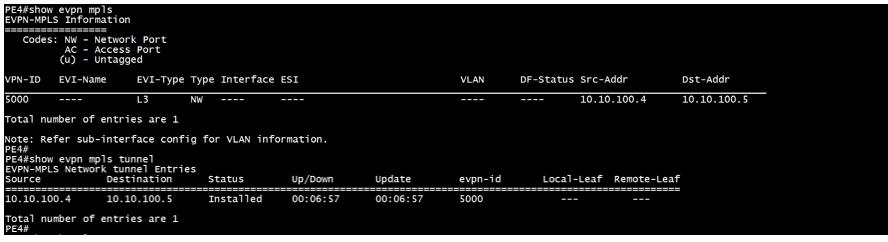
The command “show evpn mpls” checks the status of the connection, providing details such as VPN-ID, EVI-type, Source and Destination address.
The command “show evpn mpls tunnel” verifies the tunnel status between the PEs, including the EVPN ID, the tunnel’s uptime.
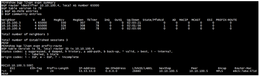
The command “show bgp l2vpn evpn summary” checks the BGP L2VPN EVPN neighbor relationship with the remote PE, including the total number of prefixes received and details of the corresponding EVPN route types. If the BGP peering is established through a Route Reflector (RR), the prefixes will be learned via the RR.
The command “show bgp l2vpn evpn prefix-route” displays the prefixes received from remote PEs.
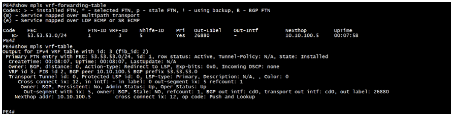
The command “show mpls vrf-forwarding-table” displays a tabular output of the VRF forwarding entries received from the remote PE via MP-BGP.
The command “show mpls vrf-table” displays a detailed output of the prefix entries received from the remote PE.
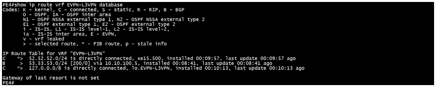
The command ‘show ip route vrf <VRF> database’ displays locally connected routes and those received remotely via MP-BGP.
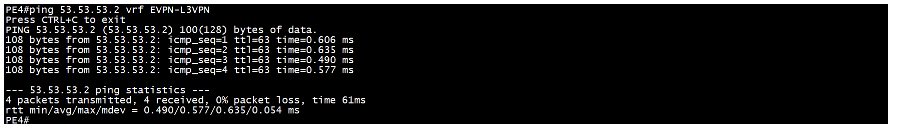
Finally, the ‘ping’ command is used to verify the reachability from the PE to remote CE devices over VRF.
Conclusion
Multi-Domain: ISIS-SR Underlay and EVPN-Based L2VPN and L3VPN Overlay offer a robust and flexible solution for modern large-scale networks. By integrating EVPN’s scalable VPN capabilities with the streamlined and adaptive traffic engineering of Segment Routing, and utilizing BGP-LU for seamless inter-domain routing, network operators can achieve enhanced scalability, efficiency, and resiliency. Implementing this integration using OcNOS ensures that networks are prepared to meet the demands of today and can adapt to future challenges with ease and reliability.
Contact us today to learn how OcNOS can offer Segment Routing for your network.

Suraj Kumar Singh is Senior Solution Lead at IP Infusion.