In the evolving landscape of MPLS networks, Segment Routing (SR) has emerged as a modern and scalable technology for traffic engineering and network programmability. This blog explores the migration from the traditional Label Distribution Protocol (LDP) to Segment Routing (SR), highlighting the benefits and practical steps involved in this transition.
Label Distribution Protocol (LDP):
LDP is a protocol used in MPLS networks to distribute and bind labels to FECs (Forwarding Equivalence Classes). It operates by establishing label-switched paths (LSPs) based on the routing information learned from IGP (Interior Gateway Protocol) protocols like OSPF or IS-IS. LDP is widely deployed and has been a fundamental mechanism for MPLS forwarding.
Segment Routing (SR):
Segment Routing leverages the source routing concept. Instead of relying on per-flow state in the network, SR encodes paths as sequences of segments. Each segment represents a forwarding instruction that directs traffic through the network. SR enhances network scalability, simplicity, and flexibility.
Benefits of Adopting SR:
Operations Simplicity: SR simplifies network operations by leveraging the source routing paradigm, reducing the need for maintaining per-flow state.
Traffic Engineering Flexibility: With SR, operators can define paths and traffic policies using segment identifiers (SIDs), enabling dynamic traffic steering.
Enhanced Resilience: SR enhances network resilience by enabling fast rerouting and path optimization.
Migration Steps from LDP to SR:
Scenario 1: When all network devices support SR
Step 0: Verification of MPLS LDP Signaling
Review “show isis topology”, “show mpls forwarding-table” and “show mpls ilm-table” on ingress/egress and transit devices respectively.
Step 1: Enablement and Verification of Segment Routing
Configure “prefix-sid” under loopback interface and “segment-routing mpls” under the IGP (ISIS or OSPF) process on all network devices. Ensure “show mpls forwarding-table” displays isis-sr entries, though not yet installed (LDP preference). Verify “show mpls ilm-table” for both isis-sr and LDP entries installed.
Step 2: SR Label Preference and Verification
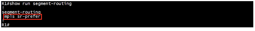
Configure “mpls sr-prefer” under segment-routing on all devices to prioritize SR labels over LDP in no specific order. By default, LDP is preferred. Confirm with “show mpls forwarding-table” that ISIS-SR entries are installed over LDP.
Step 3: Elimination of LDP and Verification
Remove LDP protocols from interfaces of SR-capable devices to transition to an SR-only underlay transport network. Preserve overlay Targeted-LDP sessions if LDP-based VPWS and/or VPLS services are still necessary.
Scenario 2: When Some Devices in the Network Lack SR Capability
Step 0: Verification of MPLS LDP Signaling
Proceed as in scenario 1.
Step 1: Enablement and Verification of Segment Routing
Follow the same steps as in scenario 1, applying configurations to all SR-capable devices.
Step 2: SRMS configuration, advertisement, and verification
Implement SRMS on one SR-capable device to assign SIDs for LDP Forwarding Table Entries (FTN). Optionally, set up SRMS on two nodes for redundancy. Detailed explanation of SRMS is provided in the subsequent section. Confirm that “show mpls ilm-table” displays SR-to-LDP stitching entries installed on SR LDP border router for all LDP-only device FEC entries.
Step 3: Prefer SR label and verification
Configure “mpls sr-prefer” under segment-routing on all devices to prioritize SR labels over LDP in no specific order. Confirm with “show mpls forwarding-table” that ISIS-SR entries are installed over LDP.
Step 4: Elimination of LDP and Verification
Remove LDP protocols from interfaces of SR-capable devices to transition to an SR-only underlay transport network. Preserve overlay Targeted-LDP sessions if LDP-based VPWS and/or VPLS services are still necessary.
Segment Routing Mapping Server (SRMS) in SR and LDP Interoperability
The Segment Routing Mapping Server (SRMS) is a pivotal component in achieving interoperability between Segment Routing (SR) and traditional Label Distribution Protocol (LDP) networks. SRMS facilitates the coexistence and gradual migration from an LDP-based MPLS infrastructure to an SR-based architecture by mapping IP prefixes to Segment Routing Global Block (SRGB) labels.
How SRMS Works
In a mixed SR and LDP environment, SRMS ensures seamless integration by performing the following functions:
Prefix-to-SID Mapping: SRMS maintains a mapping of IP prefixes for LDP only device FEC to Segment Identifiers (SIDs). These mappings are configured manually.
Advertisement via IGP: The mappings are advertised using Interior Gateway Protocols (IGPs) such as IS-IS or OSPF, which have been extended to carry SR-related information. This advertisement process ensures that all routers in SR domain can understand and utilize the mappings.
LDP Interoperability: For routers that operate purely on LDP, the SRMS ensures they receive the appropriate MPLS labels for IP prefixes. This enables LDP routers to forward packets based on traditional MPLS labels while SR-capable routers use SIDs for forwarding.
Practical Use Cases of SRMS in SR and LDP Interoperability
Gradual Network Upgrade: Service providers can use SRMS to upgrade their network incrementally. New SR-capable routers can be added to the network without disrupting the existing LDP-based operations, allowing for a smooth transition over time.
Legacy Network Integration: SRMS enables the integration of legacy LDP networks with new SR deployments. This integration allows operators to modernize their network infrastructure progressively without significant service interruptions.
OcNOS Example Scenario 1:
Step 0: Verification of MPLS LDP Signaling
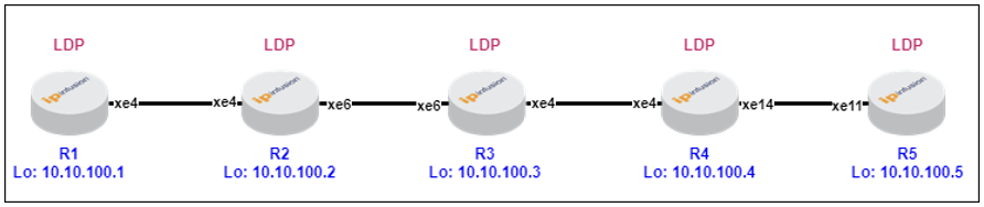
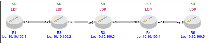
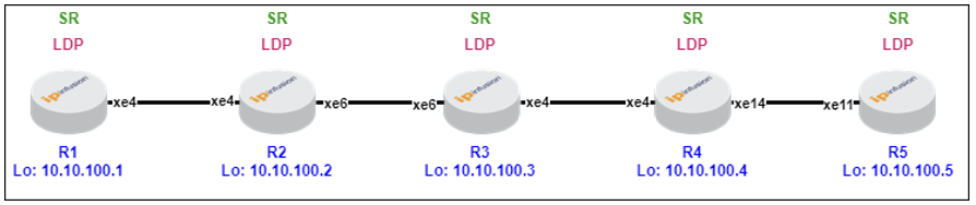
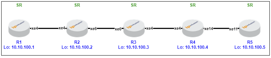
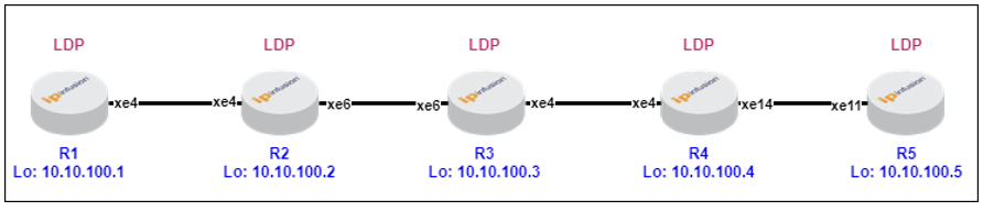
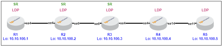
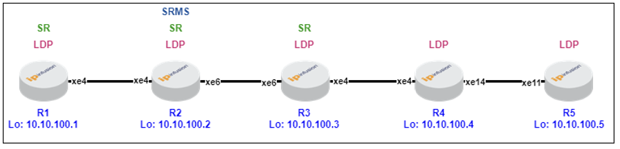
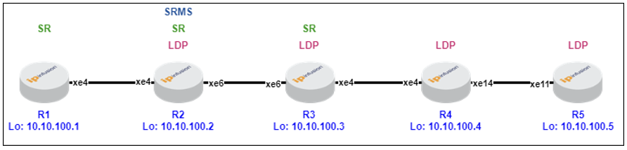
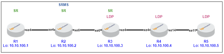
In the depicted linear topology with five routers running LDP, each router sets up LDP sessions with its adjacent neighbors to exchange and utilize MPLS labels for efficient packet forwarding.
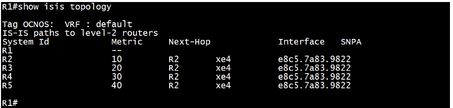
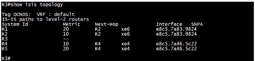
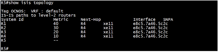
“show isis topology” provides a view of the ISIS routing domain, showing details about ISIS neighbors and the overall structure of the network.
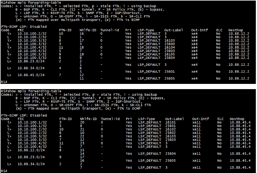
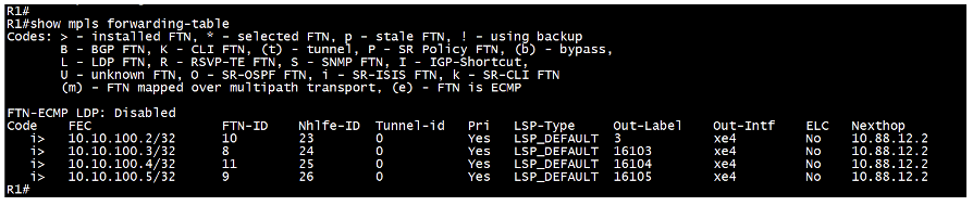
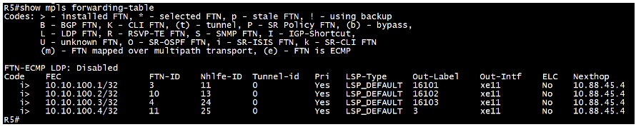
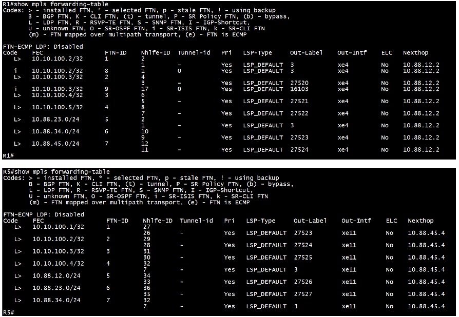
“Show mpls forwarding-table” command displays the LDP FTN, out-label and their corresponding next-hop information installed for forwarding packets in the MPLS network.
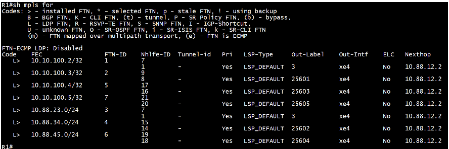
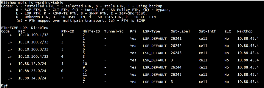
“Show mpls forwarding-table” command displays the LDP FTN, out-label and their corresponding next-hop information installed for forwarding packets in the MPLS network.
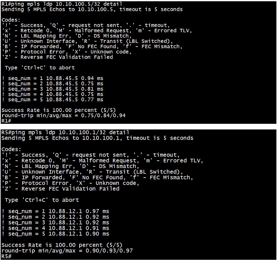
“Ping mpls ldp <destination loopback> detail” command tests the LDP connectivity to a specified destination loopback address and provides detailed diagnostic results.
Step 1: Enablement and Verification of Segment Routing
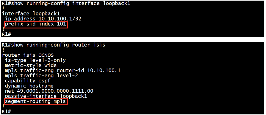
To enable Segment Routing MPLS, configure “prefix-sid” on the loopback interface and “segment-routing mpls” under the IGP on all devices, without any specific order.
“Show mpls forwarding-table” command displays the ISIS-SR FTN, out-label and their corresponding next-hop information available in control plane, but not installed, as default is LDP preferred.
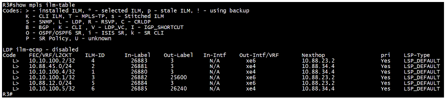
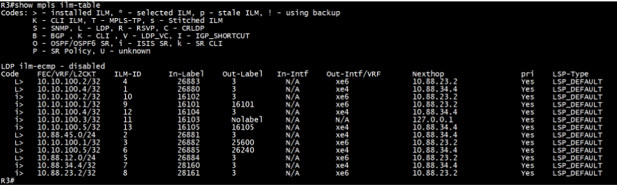
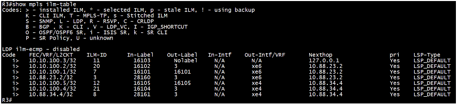
“Show mpls ilm-table” command displays the Incoming Label Map (ILM), showing mappings of incoming LDP labels to next-hop installed for forwarding packets. Here, we can see additional ISIS-SR ILM entries installed.
Step 2: SR Label Preference and Verification
Enable “mpls sr-prefer” under segment-routing configuration to prioritize Segment Routing MPLS paths over traditional LDP paths, without any specific order.
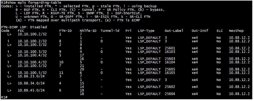
“Show mpls forwarding-table” command displays the ISIS-SR FTN, out-label and their corresponding next-hop information installed. LDP FTN entries are still available, but not installed for all loopbacks.
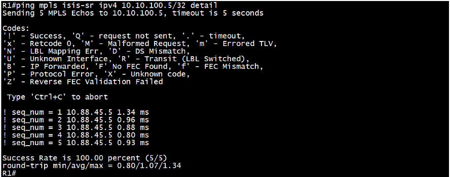
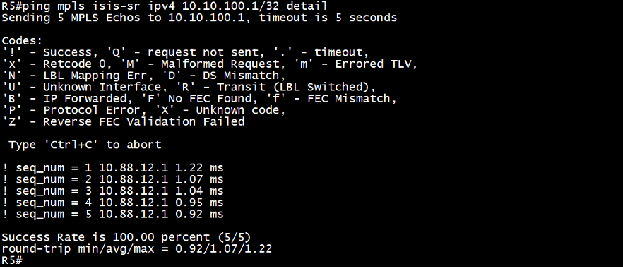
“Ping mpls isis-sr ipv4 <destination loopback> detail” command tests the ISIS-SR connectivity to a specified destination loopback address and provides detailed diagnostic results.
Step 3: Elimination of LDP and verification
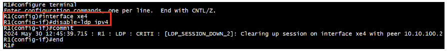
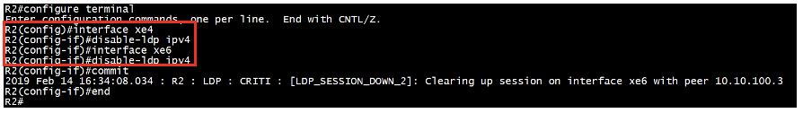
Disable LDP configuration under the interface on all devices.
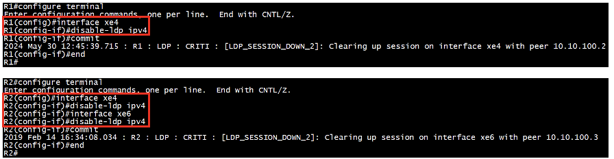
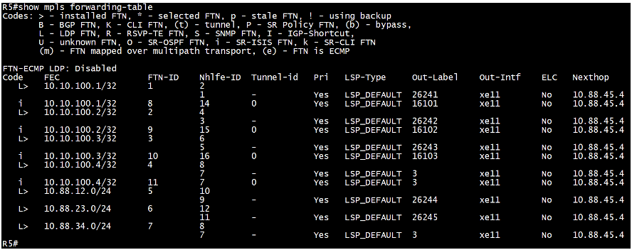
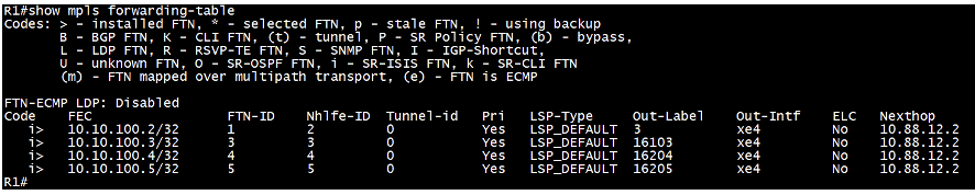
“Show mpls forwarding-table” command displays only ISIS-SR FTN, out-label and their corresponding next-hop information installed, no LDP FTN.
“Show mpls ilm-table” command displays the Incoming Label Map (ILM), showing mappings of incoming only isis-sr labels to next-hop installed for forwarding packets. No LDP ILM entries.
Disable the entire LDP process unless LDP-based VPWS/VPLS services are in use.
![]()
OcNOS Example Scenario 2:
Step 0: Verification of MPLS LDP Signaling
Proceed as in scenario 1.
Step 1: Enablement and Verification of Segment Routing
To enable Segment Routing MPLS, configure “prefix-sid” on the loopback interface and “segment-routing mpls” under the IGP on all the SR capable devices. Here R1, R2 and R3.

“Show mpls forwarding-table” command displays the ISIS-SR FTN, out-label and their corresponding next-hop information available in control plane, but not installed for R1, R2 and R3 FTN, as default is LDP preferred.
“Show mpls ilm-table” command displays the Incoming Label Map (ILM), showing mappings of incoming LDP labels to next-hop installed for forwarding packets. Here, we can see additional ISIS-SR ILM entries for R1, R2 and R3.
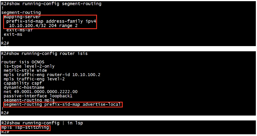
Step 2: SRMS configuration, advertisement, and verification
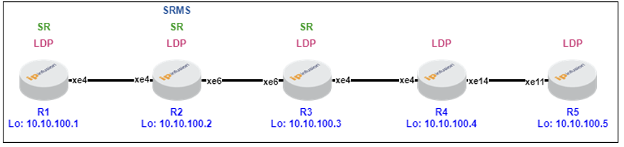
Set up SRMS on a single SR-capable device; advertise it under IGP, and activate “mpls lsp-stitching” on all SR-capable devices. Here, with “range 2,” 10.10.100.4/32 has a SID index of 104, and 10.10.100.5/32 has a SID index of 105, implying loopback and SID index incrementation according to the specified range configurations.
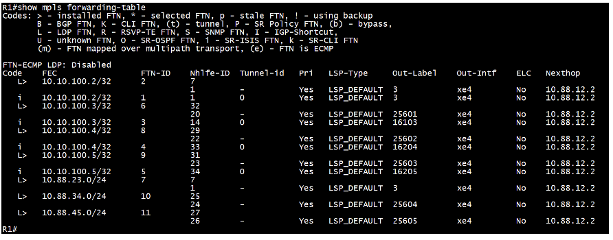
“Show mpls forwarding-table” command displays the ISIS-SR FTN, out-label and their corresponding next-hop information available in control plane, but not installed for R4 and R5 FTN as well.
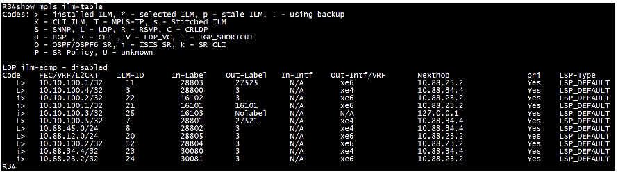
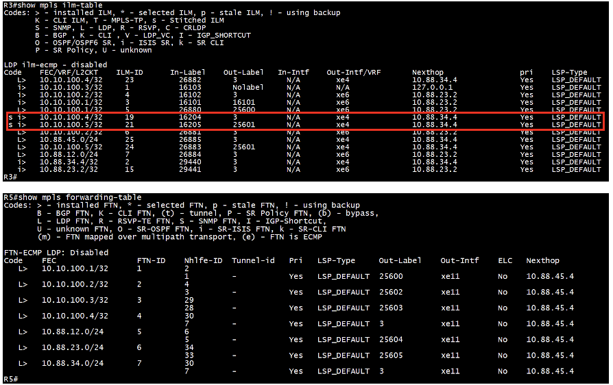
“Show mpls ilm-table” command displays the stitching Incoming Label Map (ILM), showing mappings of incoming ISIS-SR label to outgoing LDP label installed for forwarding packets. Here, we can see stitching ILM entries for R4 and R5 i.e. LDP only routers.
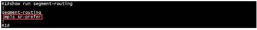
Step 3: Prefer SR label and verification
Enable “mpls sr-prefer” under segment-routing configuration on all SR-capable routers to prioritize Segment Routing MPLS paths over traditional LDP paths, without any specific sequence.
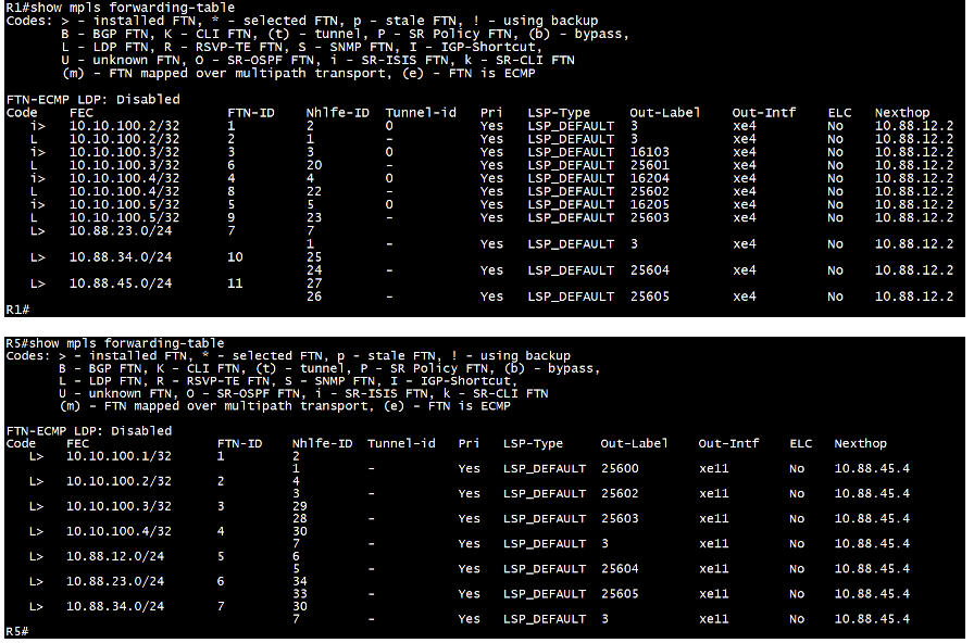
“Show mpls forwarding-table” command displays the ISIS-SR FTN, out-label and their corresponding next-hop information installed. LDP FTN entries are still available, but not installed for loopbacks.
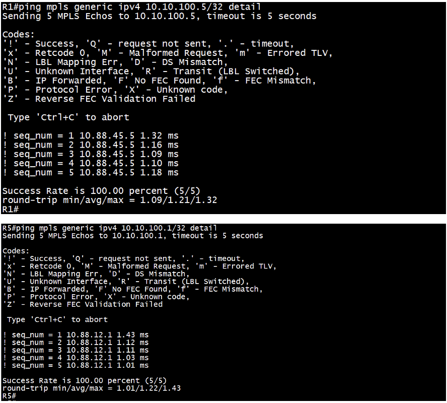
“Ping mpls generic ipv4 <destination loopback> detail” command tests the ISIS-SR to LDP and vice versa connectivity to a specified destination loopback address and provides detailed diagnostic results.
Step 4: Elimination of LDP and verification
First, we remove LDP from R1:
Disable LDP configuration under the interface on R1 device.
“Show mpls forwarding-table” command displays only ISIS-SR FTN, out-label and their corresponding next-hop information installed, no LDP FTN on R1 router.
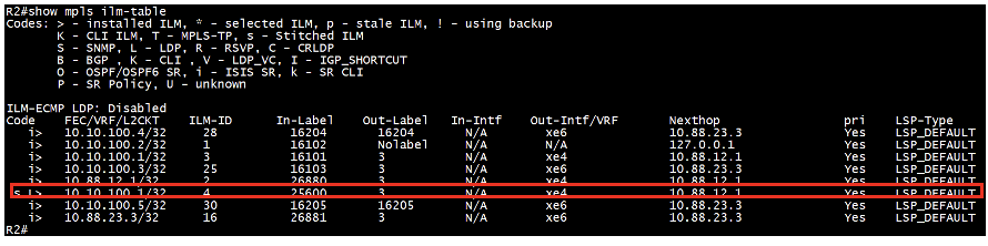
“Show mpls ilm-table” command displays the stitching Incoming Label Map (ILM), showing mappings of incoming LDP label to outgoing ISIS-SR label installed for forwarding packets. Here, we can see stitching ILM entries for R1 loopback on R2 router, as we do not have any LDP next hop to reach R1 loopback from R2.
Then we remove LDP from R2:
Subsequently, deactivate LDP configuration under the interface on the R2 device.
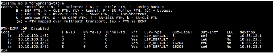
“Show mpls forwarding-table” command displays only ISIS-SR FTN, out-label and their corresponding next-hop information installed, no LDP FTN on R2 router.
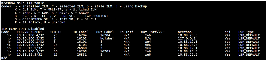
“Show mpls ilm-table” command reveals the absence of a stitching Incoming Label Map (ILM) due to R2’s unreachability via LDP from R3. As a result, the stitching entry for R1’s loopback relocates to R3, which is LDP reachable, as depicted in the subsequent output.
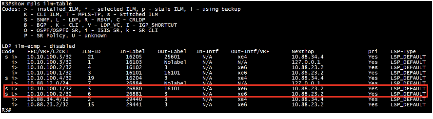
“Show mpls ilm-table” command displays the stitching Incoming Label Map (ILM), showing mappings of incoming LDP label to outgoing ISIS-SR label installed for forwarding packets. Here, we can see stitching ILM entries for R1 and R2 loopback on R3 router, as we do not have any LDP next hop to reach R1 and R2 loopback from R3.
Deactivate the entire LDP process on all SR-only running routers, except when LDP-based VPWS/VPLS services are utilized. This applies specifically to R1 and R2 in our scenario.
![]()
Conclusion
Migrating from LDP to Segment Routing (SR) with OcNOS devices signifies a strategic progression in MPLS networks, providing greater scalability and flexibility. By following a systematic approach and leveraging the advanced capabilities of OcNOS, network operators can future-proof their infrastructure and optimize network performance.
In this blog, we discussed the key concepts of LDP to SR migration and outlined practical steps for implementation. Transitioning to Segment Routing with OcNOS devices equips network operators with a cutting-edge solution, specifically designed to meet the evolving demands of modern networks.
Next Topic: EVPN-Based L2VPN and L3VPN Services over ISIS-SR.
Read our previous blogs on this topic:
Segment Routing (SR): Understanding the WHY, WHAT, and HOW
Segment Routing Extension with IGP (IS-IS) in OcNOS
Contact us today to learn how OcNOS can offer Segment Routing for your network.

Suraj Kumar Singh is Senior Solution Lead at IP Infusion.